cree焊接操作手册
摘要: Cree? LED Lamp Soldering & Handling
Cree LED Lamp Soldering & Handling
This application note applies to the following products:
P4 LEDs
Surface-mount PLCC LEDs
For XLamp LED soldering and handling information, refer to the XLamp Soldering & Handling Application Note (CLD-AP04).
This document describes how to use Cree LEDs appropriately. Generally, an LED can be used the same way as other general-purpose semiconductors. When using Cree LEDs, the following precautions must be taken to protect the LED from damage.
2-Pin and 4-Pin LEDs
1. Cleaning
When necessary, cleaning should occur only with isopropyl alcohol (IPA) at room temperature (25C) for a duration of no more than one minute. Dry at room temperature for 15 minutes before use.
The influence of ultrasonic cleaning on the LEDs depends on factors such as ultrasonic power and the way LEDs are mounted. Ultrasonic cleaning shall be pre-qualified to ensure this will not cause damage to the LEDs.
2. Forming
During lead formation, the leads should be bent at a point at least 3 mm from the base of the package.
Do not form the leads during or after soldering; if forming is required, this must be done before soldering.
Avoid stressing the LED package during leads forming.
When mounting the LEDs onto a PCB, the PCB holes must be aligned exactly with the lead position of the LEDs.
3. Soldering
A minimal cathode area of 0.18 0.18 inch2 2 is recommended for P4 LEDs.
Soldering LEDs at not less than 3 mm from the base of the package and below the tie-bar is recommended.
The LED soldering specification is shown as below (suitable for both leaded solder and lead-free solder).

Manual soldering onto a PCB is not recommended.


* Various lead-free solder types are required for different solder conditions. Please contact your Cree sales representative for details.
Do not apply any stress to the LED package, particularly when heated.
LEDs must not be re-used once extracted from a PCB.
After soldering the LEDs, the package should be protected against mechanical shock or vibration until the LEDs have reached 40C or below.
Mechanical stress on the LEDs may cause PCB warpage, clinching or cutting of the LED leads.
When clamping LEDs during soldering is required, be sure that no mechanical stress is exerted on the LEDs.
Lead cutting must be performed at normal room temperature (25C). Lead cutting at an elevated temperature can cause LED failures.
4. Electrostatic Discharge and Surge Current
Electrostatic discharge (ESD) or surge current (EOS) can damage LEDs.
An ESD wrist strap, ESD shoe strap or antistatic gloves must be worn whenever handling LEDs.
All devices, equipment and machinery must be properly grounded.
Electrical tests to screen out ESD failures should be performed at final inspection.
Eliminate the possibility of surge current during circuitry design.
5. Heat Management
Heat management of LEDs must be taken into consideration during the design stage of LED application. The current should be de-rated appropriately by referring to the de-rating curve found in each product specification.
The temperature surrounding the LED in the application should be controlled. Please refer to the data sheet de-rating curve.
6. Others
Reverse voltage should not exceed the absolute maximum rating on the data sheet.
The LED leads may become tarnished if they contact hydrogen sulfide or other gaseous chemicals.
Precaution must be taken to maintain a clean storage atmosphere.
High-brightness LED light may injure human eyes. Avoid looking directly into lighted LEDs.
SMD LEDs
1. Cleaning
When necessary, cleaning should occur only with isopropyl alcohol (IPA) at room temperature (25C) for a duration of no more than one minute. Dry at room temperature for 15 minutes before use.
The influence of ultrasonic cleaning on the SMD LED depends on factors such as ultrasonic power and the way the SMD LEDs are mounted. Ultrasonic cleaning should be pre-qualified to ensure this will not cause damage to the SMD LEDs.
2. Moisture-Proof Packing
To prevent moisture absorption into SMD LEDs during the transportation and storage, the LEDs are packed in a moisture-barrier bag. Desiccants and a humidity indicator are packed together with the LEDs as secondary protection.
A humidity-indicator card inside the packing indicates the humidity level.
3. Storage
The shelf life of LEDs stored in the original sealed bag at <40C and <90%RH is 12 months. Baking is required if the shelf life has expired.
Before openning the packaging, check for air leaks in the bag.
After the bag is opened, the SMD LEDs must be stored at < 30C and < 60% RH. Under these conditions, SMD LEDs must be used (subject to reflow) within 24 hours. If the LEDs are not within 24 hours after removal from the bag, baking is required.
To bake, place the SMD LEDs in an oven at 80C 5C and relative humidity ≤10% RH for 24 hours.
Take the material out of the packaging bag before baking. Do not open the oven door frequently during the baking process.
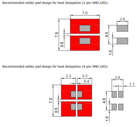
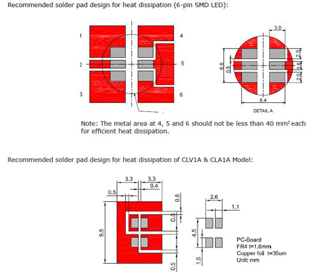
4. Soldering
a. Manual Soldering with a Soldering Iron
Use of a soldering iron of less than 25 watts is recommended. The iron temperature must be kept below 315C and soldering time no more than 2 seconds.
The epoxy resin of an SMD LED should not contact the tip of the soldering iron.
No mechanical stress should be exerted on the resin portion of an SMD LED during soldering.
Handling of an SMD LED should be done only when the package has been cooled down to below 40C or less. This is to prevent SMD LED failures due to thermal-mechanical stress during handling.
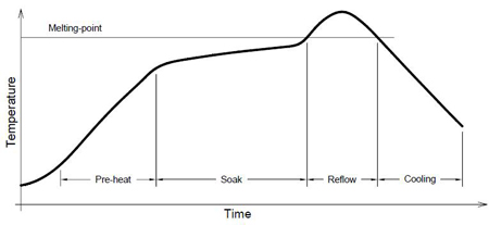
b. Reflow Soldering
Temperature (top surface of the SMD LED) profile:


SMD LEDs should not be modified after soldering. If modification cannot be avoided, the modifications must be pre-qualified to avoid damaging the SMD LEDs.
Reflow soldering should not be done more than one time.
No stress should be exerted on the package during soldering.
The PCB should not be wrapped after soldering; allow the PCB board and SMD LED to cool naturally.
5. Important Notes (Small Top & Mini side 0.8 mm SMD product)
The packaging sizes of these SMD products are very small and the resin may still be soft after solder reflow. Users are required to handle with care; never touch the resin surface of the SMD products.
To avoid damaging surface and interior device of these SMD LEDs during SMT production, choose a special nozzle to pick up the SMD products. If handling is necessary, take care picking up these products. The following two methods are recommended:
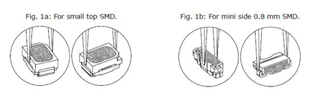
For small top SMDs, use a rubber nozzle to pick up the LEDs. Here are two sizes for reference:
a) Circular nozzle inner diameter: 1.8 mm 0.05 mm; outer diameter: 2.3 mm 0.05 mm.
b) Rectangular nozzle inner size: 1.3 mm x 2.3 mm; outer size > SMD size.
6. Electrostatic Discharge and Surge current
Electrostatic discharge (ESD) or surge current (EOS) can damage LEDs.
An ESD wrist strap, ESD shoe strap or antistatic gloves must be worn whenever handling LEDs.
All devices, equipment and machinery must be properly grounded.
Electrical tests to screen out ESD failures should be performed at final inspection.
Eliminate the possibility of surge current during circuitry design.
7. Heat Management
Heat management of SMD LEDs must be taken into consideration during the design stage of SMD LED application. The
current should be de-rated appropriately by referring to the de-rating curve attached to each product data sheet.
凡注明为其它来源的信息,均转载自其它媒体,转载目的在于传递更多信息,并不代表本网赞同其观点及对其真实性负责。
用户名: 密码: